MEAP 4b hardware description
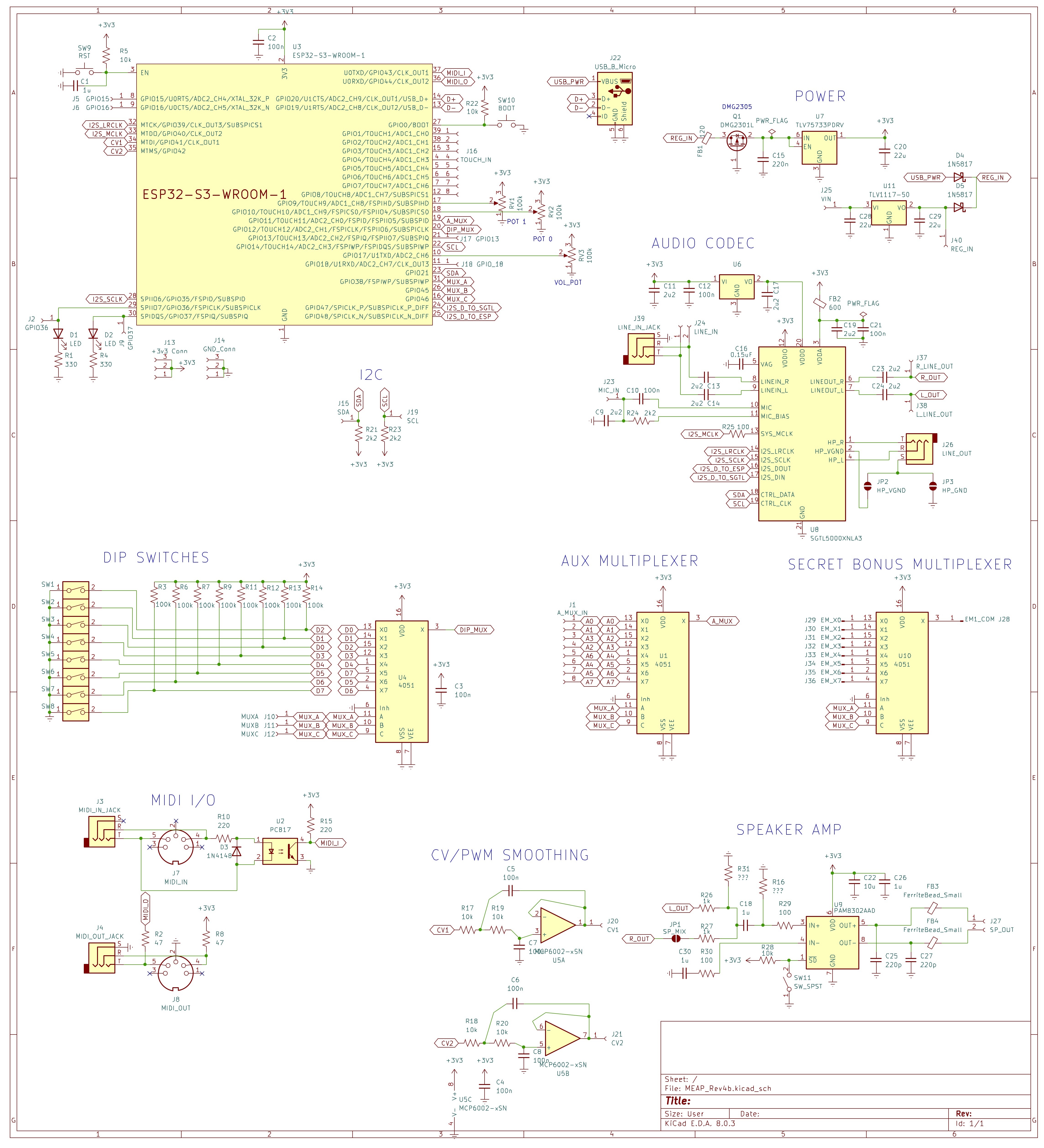
MEAP's circuit board was designed using the fantastic open source softwareKicad. If you really want to know what is going on in the hardware world of MEAP, the best way is to open the design files (which are located within the hardware design folderon the MEAP Github) in Kicad, however this page will provide a surface level summary.
important chips used:
- ESP32-S3-WROOM-1-N16R8: the microcontroller
- SGTL5000: the audio codec
- PAM8302: the speaker amp
Schematic

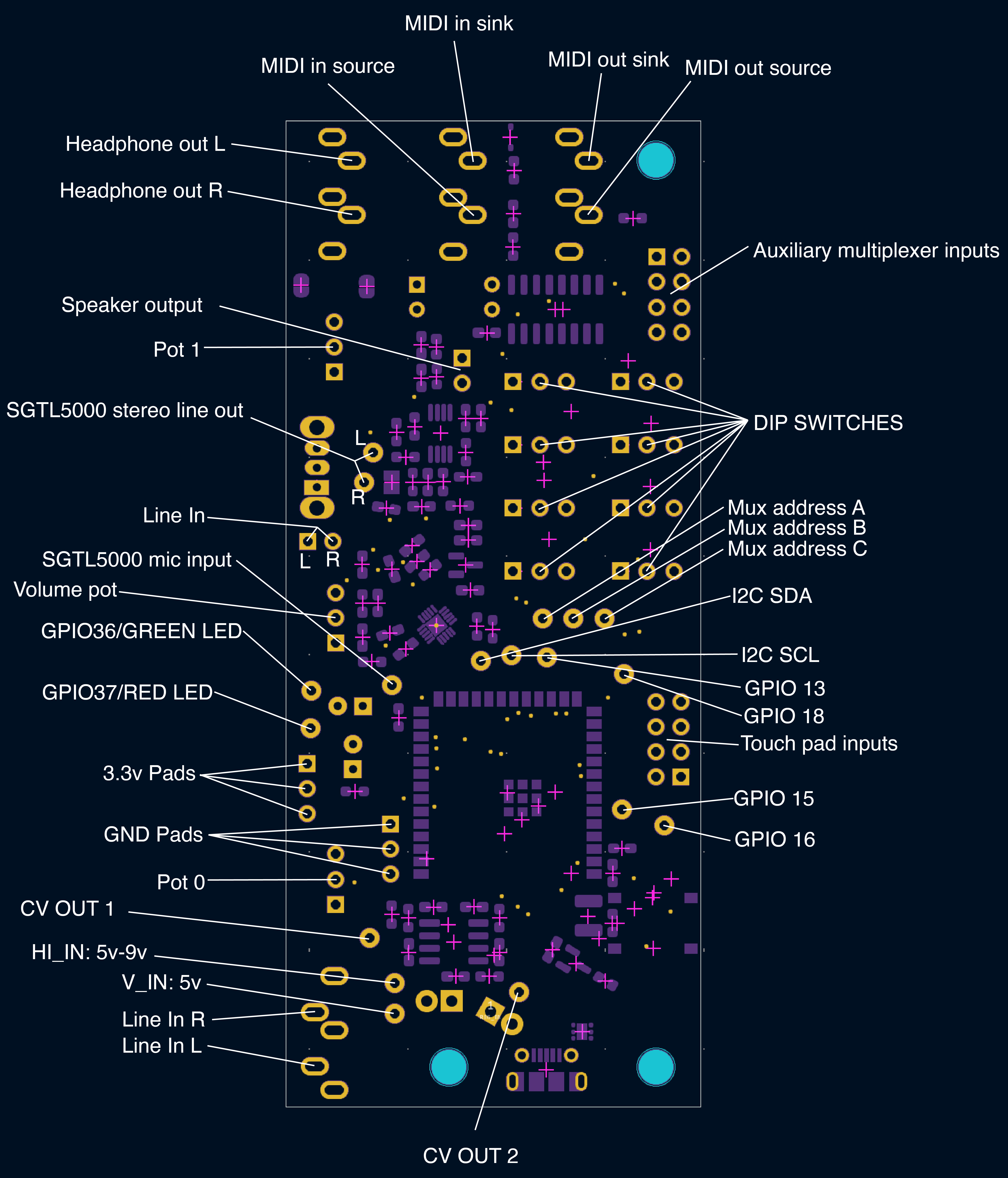
PCB Pads

Hackable bits
Auxiliary multiplexer
MEAP has one built-in multiplexer you can use to connect more analog (continuously variable like a potentiometer) or digital (on/off like a button) signals without adding any extra circuitry. All you need to do is solder the data signal of whatever device you are connecting to the 2x4 grid of pins to the right of your MEAP's DIP switches as shown below. The output of this multiplexer is connected to GPIO pin 11.
._ ._|0|/1\
|_|\_/
._ ._
/3\/2\
\_/\_/
._ ._
/6\/4\
\_/\_/
._ ._
/5\/7\
\_/\_/
Secret bonus multiplexer pads
The back side of the MEAP board contains pads for an extra multiplexer (74LV4051D in SOIC16 3.9mmx9.9mm package). It is connected to the same address pins as all other multiplexers on the board. If it is used, it is recommended to add strain relief(eg. hot glue) to any wires soldered to the surface mount pads.
Unused GPIO Pins
Several unused GPIO pins are broken out for analog/digital input or output.
- GPIO 13
- GPIO 15
- GPIO 16
- GPIO 18
Repurposing used GPIO Pins
If you need more pins for your project, some of the pins used by MEAP can be repurposed without too much trouble.
- LED pins:
GPIO 36 and 37 control the green and red LEDs respectively. If you want to free up these pins, just desolder the LEDs and they can be used as GPIOs. Additional pads are broken out next to the LEDs for ease of soldering. For some use cases, you may not even need to remove the LEDs.
- Touch pins:
If you are willing to forgo your touch keyboard, all eight of the pins used by it would be freed up. These are GPIO 1 through GPIO 8 in the below order. All can be used as analog or digital inputs or outputs. If you do so, you will likely want to stop using the Meap::readInputs() function and create your own alternative that doesn't read those pins as capacitive touch inputs.
._ ._
/8\/7\
\_/\_/
._ ._
/6\/5\
\_/\_/
._ ._
/4\/3\
\_/\_/
._ ._
/2\|1|
\_/|_|
I2C Pins
GPIO pins 21 (SDA) and 14 (SCL) are configured as an I2C port which is used to configure the audio codec. Other I2C devices can be added to the same data and clock lines. You could mayyyybe use these pins for other purposes so long as they are still able to send messages to the audio codec on boot.
Adding additional multiplexers
The multiplexer address pins A, B and C are broken out on the board. These can be connected to any other 8-channel multiplexers wired on auxilliary circuit boards for additional inputs.
External power
If you have an external 5v power supply you want to use to power your MEAP, you can solder it directly into the V_IN pin. The back of the board contains pads to solder on a power regulator for any external power source over 5v. A TLV1117-50 along with two 22uF 1210 ceramic capacitors can be soldered on to use this. The external power source that needs to be regulated can be soldered onto HI_IN and GND. Input voltage can technically be up to 16V but I wouldn't recommend going above 9. I have not had great success with getting smooth power out of this regulator so I've been happy sticking to USB power for now!
SGTL5000 Bonus I/O
The audio codec chip used has two separate outputs whose volume can be controlled independently.
- Headphone out: sent to the 3.5mm jack labelled "line out". Technically it is not a line level signal, its voltage is a little low, but it can be connected to most mixers without too much trouble.
- Line out: sent to the internal speaker. If you wanted a true line out from your MEAP, you may be able to hook into the Line Out pads on the board. This is currently untested, and there is a chance the output levels/impedance would be wrong because this output is also connected to the speaker amp.
The audio codec chip also has two inputs, but only one can be active at a time.
- Line in: default input, connected to the 3.5mm jack labelled "Line In".
- Mic: condenser capsule input, with bias voltage. A sample circuit can be found in the SGTL5000 datasheet pg. 60